How OpenAI delivers low-latency voice AI to 900 million users
Voice AI feels natural only when it responds within ~300ms. This post unpacks how OpenAI rearchitected its WebRTC infrastructure to hit that bar at the scale of ChatGPT voice: a relay + transceiver split that keeps public UDP surface tiny, encodes routing metadata into a protocol-native field for first-packet routing, and geo-steers users to nearby ingress points worldwide.
Ready to ace your system design interview?
This article is just one piece. SWE Quiz gives you structured, interview-focused practice across every topic that comes up in senior engineering rounds.
- 1,000+ quiz questions across system design and ML/AI
- Spaced repetition to lock in what you learn
- Full case study walkthroughs of real interview topics
- Track streaks, XP, and progress over time
TL;DR
- Human conversation breaks down above ~300ms end-to-end latency. Voice AI systems must be designed around this hard perceptual threshold, not just general performance goals.
- WebRTC solves the hard problems of real-time audio: NAT traversal (ICE), encrypted UDP transport (DTLS + SRTP), codec negotiation, echo cancellation, and jitter buffering, but its one-port-per-session model does not scale on Kubernetes.
- OpenAI chose a transceiver model (full session termination) over an SFU (packet forwarding) because AI must decode and process audio, forwarding raw packets is useless when the "other party" is an inference pipeline.
- A relay + transceiver split solves the port explosion problem: a thin relay with a fixed small UDP footprint routes traffic to stateful transceiver pods by reading the ICE username fragment (ufrag) from the unencrypted packet header.
- The relay encodes the destination transceiver address directly into the ICE ufrag during session setup, enabling deterministic first-packet routing with no external state lookup and a tiny public attack surface.
Why this matters for interviews
Real-time voice AI architecture sits at the intersection of three interview domains: low-latency distributed systems, transport protocol design, and AI inference pipelines. The relay/transceiver split is a clean instance of the control plane vs. data plane separation pattern that interviewers probe in system design. The perceptual latency threshold gives you a concrete design constraint to anchor the conversation.
Breakdown
1.Why voice latency is not like API latency
Most backend systems treat latency as a performance metric: lower is better, but 200ms vs. 500ms rarely breaks a feature. Voice AI is different because of how humans perceive conversation. Above roughly 150ms of round-trip delay, people start to notice. Above 300ms end-to-end, turn-taking breaks down: speakers interrupt each other, there are awkward silences, and the conversation feels like a satellite phone call. This is not a soft preference, it is a hard perceptual constraint rooted in human auditory processing.
The end-to-end budget for a voice AI response looks like this: the user speaks, audio is captured and encoded on the device, it travels over the network to the server, a voice activity detector identifies the end of the utterance, a speech-to-text model transcribes it, a language model generates a response (streaming tokens), a text-to-speech model synthesizes speech, audio travels back over the network, and the client decodes and plays it. Each stage adds latency. You have roughly 300ms to do all of this.
Two things make this tractable. First, you can pipeline: start transcribing while the user is still talking, start synthesizing as soon as the first sentence of the LLM output arrives. Second, you can use native audio models like GPT-4o that bypass the ASR and TTS stages entirely by processing audio end-to-end. But the transport layer, getting audio to and from the server, is the first problem to solve, and it sets a floor that no model optimization can lower.
Interview angle: Interviewers often start with "design a voice AI system" and then follow up with "how do you hit your latency target?" The right answer starts with a concrete budget: name the 300ms threshold, break down where each millisecond goes (network round-trip, transcription, first-token latency, TTS synthesis), and then explain how pipelining and streaming reduce the effective perceived latency even when total processing time exceeds the budget.
2.WebRTC from zero: why it exists and what it actually does
WebRTC (Web Real-Time Communication) is a collection of standards that make real-time audio and video communication work from a browser or native app. Before WebRTC, building a video call required proprietary plugins or native apps because browsers had no standard way to handle real-time media. WebRTC solves several hard problems that a naive "just send audio over a WebSocket" approach would leave unresolved.
The first hard problem is connectivity. Most devices are behind NAT (Network Address Translation) routers and firewalls. Two devices cannot directly connect to each other without a way to discover and test candidate network paths. WebRTC uses ICE (Interactive Connectivity Establishment) for this: both sides gather candidates (local IP addresses, translated IP addresses via STUN servers, and relayed addresses via TURN servers), exchange them via a signaling channel (typically HTTP or WebSocket), and then test each candidate pair to find one that works. This is NAT traversal.
The second hard problem is encrypted transport. WebRTC uses DTLS (Datagram Transport Layer Security, the UDP equivalent of TLS) to negotiate encryption keys, and then wraps all media in SRTP (Secure Real-Time Transport Protocol). Every packet is encrypted. Wiretapping or injection attacks on the media stream are not possible once the session is established.
The third hard problem is media quality over an unreliable network. WebRTC uses UDP, not TCP, for media. TCP guarantees delivery by retransmitting lost packets, but retransmission introduces unpredictable delay, if a packet is dropped at 100ms and retransmitted at 300ms, all subsequent packets queue behind it (head-of-line blocking). For voice, it is better to drop a 20ms audio frame than to play audio 200ms late. WebRTC uses codec-level packet loss concealment to hide brief gaps, a jitter buffer to smooth out arrival time variation, and RTCP (RTP Control Protocol) for quality feedback and adaptive bitrate. Opus, the standard WebRTC audio codec, can operate at 6 to 510 kbps and handles packet loss gracefully.
The fourth hard problem is client-side audio processing. Browser implementations of WebRTC include built-in acoustic echo cancellation (so the speaker output does not feed back into the microphone), noise suppression, and automatic gain control. These run on the client before audio ever reaches the server, a meaningful reduction in the work the AI pipeline needs to do.
Interview angle: An interviewer who asks "why WebRTC instead of WebSocket?" is probing whether you know that TCP's retransmission behavior is actively harmful for real-time media. The correct answer: for voice, dropping a packet is better than delaying all subsequent packets. UDP + SRTP + jitter buffer + loss concealment is a better tradeoff than TCP for latency-sensitive streams. WebSocket is fine for signaling (SDP exchange, session control) but wrong for the media plane.
3.The Kubernetes problem: one UDP port per session does not scale
In a standard WebRTC server deployment, the server must expose a public UDP port for each active session. A client connects to a unique port, and that port is bound to the server process handling that session. This is fine at small scale. At OpenAI's scale, hundreds of millions of weekly users, with many concurrent voice sessions at any given time, it creates three serious operational problems.
First, Kubernetes and cloud load balancers are not designed to expose tens of thousands of UDP ports. NodePort services in Kubernetes support a range of roughly 30,000 ports (30000 to 32767 by default). For applications that require one port per session, this is a hard ceiling. You can work around it with host networking (bypassing Kubernetes's network model entirely), but then you lose the benefits of service discovery, autoscaling, and standard network policies.
Second, a large public UDP port range is a security liability. Every exposed port is an attack surface. Scanning for open ports is trivial, and UDP-based amplification attacks target open ports. A smaller and more predictable UDP footprint is easier to firewall, monitor, and harden.
Third, port reservations conflict with autoscaling. If a pod owns a port range and that pod needs to be replaced or scaled up, you need to coordinate port assignments across the cluster. This couples the stateful port assignment problem to the stateless compute scaling problem, two things that are much easier to reason about separately.
Interview angle: This is the setup for the relay/transceiver solution. In an interview, if you propose "just run WebRTC servers in Kubernetes," a strong follow-up question is "how do you handle UDP port assignment at scale?" Knowing that this is a real problem, and not just a hypothetical, and that the solution is to decouple the public UDP surface from session state, is exactly what differentiates a candidate who has thought about production deployment from one who has only thought about the happy path.
4.SFU vs. MCU vs. transceiver: picking the right server model
There are three fundamentally different models for how a server participates in a real-time media session, and the choice has major implications for latency, compute cost, and what the server can actually do with the audio.
A Multipoint Control Unit (MCU) decodes all incoming media streams, mixes them into a single composite stream, and re-encodes it for each participant. Every participant receives one stream regardless of how many others are in the call. This is the traditional conference call model. The tradeoff: the server must decode and re-encode, which is compute-intensive and adds latency. MCUs were common in the early days of video conferencing.
A Selective Forwarding Unit (SFU) is the dominant model in modern multi-party systems like Zoom, Google Meet, and WebRTC-based conferencing. The SFU forwards media packets between participants without decoding them. Each participant receives streams from all others. The server is essentially a smart router, it can apply routing policy (simulcast, bandwidth adaptation) but never decodes the actual content. This is very compute-efficient.
A transceiver is a server that fully terminates a WebRTC session and participates as a genuine peer. It maintains ICE state, holds DTLS encryption context, decodes the audio, and then does whatever it wants with the raw PCM, in OpenAI's case, that means feeding it to an ASR model or a native audio model. It produces a response and re-encodes it for transmission back to the client.
OpenAI chose the transceiver model, and for voice AI this is the only model that makes sense. An SFU is designed to forward packets from human speaker A to human speaker B. The AI is not a passive participant receiving packets, it needs to actively process the decoded audio and generate a response. An SFU would forward packets to an AI backend that still has to decode them. The transceiver just does all of this in one place. There is also a latency argument: a transceiver can begin processing audio as it arrives (before the utterance ends), enabling streaming transcription and early response generation.
Interview angle: If an interviewer asks "how would you design the server component?", naming the three models and explaining the choice signals depth. The key insight: SFUs are optimized for the N:N human-to-human case where the server should be transparent. AI voice calls are 1:1, and the AI must process the audio. Transceiver is right. A common mistake is proposing an SFU because it sounds more scalable, but an SFU that still forwards to an AI backend for decoding is just a transceiver with extra hops.
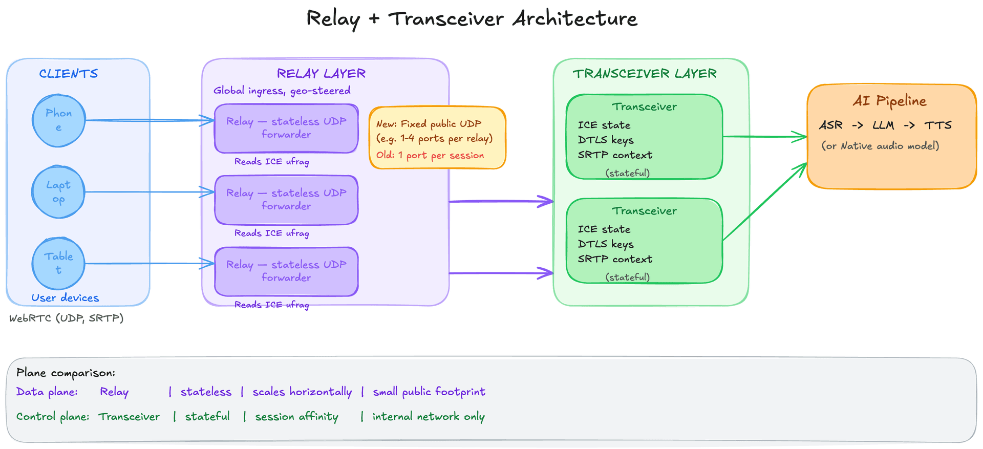
5.The relay + transceiver split: separating the public surface from session state
Even after choosing the transceiver model, the port explosion problem remains. Each transceiver pod needs to expose a public UDP port per session. OpenAI's solution is to split packet routing from protocol termination into two separate services.
The relay is a lightweight UDP forwarding service. It exposes a small, fixed set of public UDP ports, potentially just one or a handful per relay instance. Every incoming WebRTC packet from any client arrives at the relay first. The relay's only job is to read a routing identifier from the packet and forward it to the correct transceiver pod on the internal network. Critically, the relay does not decrypt any media, it reads metadata from the unencrypted portion of the packet header and forwards the raw bytes. This makes it stateless from a media perspective and extremely fast.
The transceiver runs on the internal network with no public UDP exposure. It maintains full WebRTC session state: the ICE connectivity state, the DTLS encryption context, the SRTP keys, and the upstream connection to the AI inference backend. It is the stateful, compute-intensive component. Because it only receives traffic from the relay (not directly from the internet), it does not need to expose any ports publicly. Multiple transceiver pods can run behind standard Kubernetes services.
The architecture separates two concerns that were previously coupled: the relay manages the public UDP surface (a small, fixed, hardened attack surface), and the transceiver manages session state (stateful, but not publicly exposed). The relay scales horizontally as a stateless forwarder. The transceiver scales by session affinity, clients are routed to the transceiver that owns their session.
This split is a specific instance of the broader data plane vs. control plane separation pattern. The relay is the data plane: it moves packets fast without caring about their content. The transceiver is the control plane: it manages state, makes decisions, and connects to backend services.
Interview angle: This is one of the most transferable patterns in the article. Data plane vs. control plane separation appears in load balancers (L4 forwarding vs. L7 routing), service meshes (sidecar proxy vs. control plane), and CDNs (edge forwarding vs. origin logic). In an interview, naming this pattern and connecting the specific implementation to the broader concept demonstrates architectural maturity.
6.The ICE ufrag trick: first-packet routing without external lookups
The relay needs to know which transceiver to forward each packet to. The naive approach would be to maintain a lookup table: incoming packet arrives, relay queries a central store keyed on source IP + port, gets back the transceiver address, forwards. This works but adds a round-trip for every forwarding decision and introduces a dependency on an external stateful service (the lookup table) in the critical path.
OpenAI's approach is more elegant. When a client establishes a WebRTC session, it goes through SDP (Session Description Protocol) negotiation: the client and server exchange a text description of the session parameters (codecs, ICE candidates, ICE credentials). One of the values in this exchange is the ICE ufrag, a short identifier that appears in every STUN packet during the ICE process. STUN packets are unencrypted during the connectivity phase, so the relay can read the ufrag without decrypting anything.
During session setup, the signaling layer encodes the target transceiver's address directly into the ICE ufrag. When the client's first STUN packet arrives at the relay, the relay reads the ufrag, parses the embedded transceiver address, and forwards the packet, no external lookup, no state, no round-trip. The routing metadata travels with the packet itself, inside a field that is already part of the WebRTC protocol.
This is a clean application of a general principle: when you need to route traffic, prefer embedding routing metadata in the traffic itself over maintaining external routing tables. It also means the routing logic is deterministic: the same ufrag always routes to the same transceiver, regardless of the relay instance that receives the packet. This makes the relay fully stateless.
Interview angle: This is a strong answer to the interview question "how would you avoid a round-trip lookup in your routing layer?" The principle, encode routing decisions in the packet itself using a protocol-native field, also appears in consistent hashing (hash the key to determine the shard), in HTTP routing (route on URL path or host header without external state), and in anycast routing (embed topology information in the IP address). Knowing that the ufrag is unencrypted during the ICE phase is the specific WebRTC fact that makes this possible.
7.Going global: reducing first-hop latency with geo-steered ingress
The relay + transceiver architecture solves the Kubernetes port problem, but it does not automatically make the system fast for users everywhere. If the only relay nodes are in US-East, a user in Tokyo still has ~150ms of one-way network latency before their audio reaches the relay, before any processing has even started.
OpenAI deploys relay nodes at geographically distributed ingress points around the world. For signaling (the SDP negotiation that happens before any media flows), they use Cloudflare's geo-steering: DNS returns the address of the nearest signaling endpoint based on the user's location. The user's first network hop, the one they have the least control over, goes to a nearby relay node rather than to a distant data center.
Once the session is established, media from the client flows to the nearby relay, which forwards it over OpenAI's internal backbone to the transceiver and inference backend. Internal backbone routing is faster and more reliable than public internet routing, so the net result is that the highest-latency part of the path (the last-mile hop from client to server) is minimized.
The separation of relay and transceiver is what makes this practical. The relay is stateless and cheap to deploy globally. The transceiver is stateful and computationally expensive, you do not want to deploy GPU inference capacity at every relay PoP. The geo-distributed relay nodes act as low-latency onramps onto the backbone, and the expensive processing happens centrally. This is the same topology CDNs use: edge nodes close to users for fast delivery, origin servers for the actual content.
Interview angle: The CDN analogy is worth naming explicitly in interviews: "think of the relay nodes as CDN edge nodes and the transceivers as origin servers." The pattern is well-understood in that context and immediately communicates the tradeoff. The follow-up question is usually "what happens if the user's nearest relay is different from the transceiver that holds their session state?" Answer: the relay is stateless and routes by ufrag, so the same session can be served from any relay without that relay knowing anything about the session.
8.Socket-level performance: SO_REUSEPORT and cache locality
Even with good architecture, a poorly implemented UDP relay can become a bottleneck. A single thread reading from a single UDP socket can process only so many packets per second, not because of bandwidth, but because of CPU time per packet (system calls, memory copies, scheduling).
OpenAI's relay uses two Linux socket options to maximize throughput without needing kernel-bypass frameworks like DPDK. The first is SO_REUSEPORT, which allows multiple threads to bind to the same UDP port. The Linux kernel then distributes incoming packets across all bound threads using a hash of the source IP and port. Each thread has its own socket file descriptor and processes its own stream of packets in parallel. This turns a single-threaded bottleneck into a parallelizable workload.
The second is runtime.LockOSThread (this is Go-specific). Normally, Go's scheduler can move a goroutine between OS threads. For a tight packet processing loop, this is bad for CPU cache performance: if a goroutine moves to a different OS thread, the socket state and packet buffers that were warm in the previous CPU's cache must be re-fetched. LockOSThread pins the goroutine to its OS thread, preserving cache locality across the packet processing loop.
The result is a relay that handles high packet throughput using standard kernel networking, without the complexity of DPDK or io_uring. This is worth noting because kernel-bypass frameworks are sometimes proposed for high-performance network services, but they add significant operational complexity. At voice AI packet rates (audio is not high-bandwidth), standard kernel networking with SO_REUSEPORT is sufficient.
Interview angle: SO_REUSEPORT is a useful detail to know for any system that must receive high-throughput UDP at a single port (DNS servers, game servers, real-time media servers). If an interviewer asks "how would you scale a UDP server beyond a single CPU core?", SO_REUSEPORT is the correct kernel-level answer. The broader point, that cache locality matters for tight network loops, is relevant whenever you are reasoning about per-core performance in latency-sensitive systems.
9.Interview walkthrough: "Design a real-time voice AI system"
This is a composite system design question that combines real-time media infrastructure with AI inference. Here is how to structure a strong answer.
**Step 1: Clarify requirements and constraints.** Before drawing anything, nail down: what is the latency target? (Answer: sub-300ms end-to-end for natural conversation.) What platforms must be supported? (Web and mobile.) What is the expected scale? (Say 1 million concurrent sessions.) Is this a native audio model or a pipeline (ASR + LLM + TTS)? These answers shape every subsequent decision.
**Step 2: Sketch the high-level flow.** Client speaks into a microphone. Audio is captured and encoded on the device. It travels over WebRTC (UDP, SRTP, Opus) to the nearest relay node. The relay forwards to a transceiver, which decodes the audio and feeds it to the AI pipeline. The pipeline returns synthesized speech. The transceiver encodes it and sends it back through the relay to the client.
**Step 3: Deep dive on transport.** Justify WebRTC over WebSocket: you need UDP to avoid head-of-line blocking, SRTP for encryption, and jitter buffering for smooth playback. The client gets these for free in browser WebRTC. Use Opus codec for high-quality audio at 16-32 kbps.
**Step 4: Deep dive on server architecture.** Propose the relay + transceiver split. The relay is a stateless UDP forwarder with a small fixed port footprint, deployed globally as geo-steered ingress. The transceiver handles full WebRTC session termination and connects to the AI backend. Encode the transceiver address in the ICE ufrag for first-packet routing. This gives you: a small, auditable attack surface; relay nodes that scale as stateless compute; transceivers that scale by session affinity.
**Step 5: Deep dive on the AI pipeline.** Name the three options: pipeline (Whisper + GPT-4 + TTS), streaming pipeline (overlap each stage), or native audio model (GPT-4o audio mode). For minimum latency, streaming is critical: begin transcribing as the user speaks, begin synthesizing as the first sentence of the LLM response arrives. If using a native audio model, the pipeline overhead disappears but you trade off per-stage control.
**Step 6: Latency budget.** Walk through the budget explicitly: ~20-50ms network (user to nearest relay), ~50-100ms first-token from model, ~50ms TTS first audio chunk, ~20ms network back. With pipelining, perceived response time can be under 200ms even if total pipeline time is longer. The key metric for perceived responsiveness is time to first audio byte, not total response latency.
**Step 7: Name the tradeoffs you consciously made.** Relay adds one extra network hop vs. direct transceiver exposure, but the security and operational benefits outweigh it. Centralized transceivers add ~10-20ms backbone latency vs. fully distributed, but avoid the cost of running GPU inference at every edge PoP. Choosing native audio model reduces pipeline latency but reduces per-stage observability and control.
Interview angle: The most common mistake in this interview question is spending too long on the AI model and not enough on the transport layer. Interviewers for infrastructure or distributed systems roles often ask this specifically to probe whether you understand real-time media constraints. Starting with the 300ms perceptual threshold and the WebRTC + relay + transceiver architecture before discussing the model signals that you understand the full system.
Key Concepts
WebRTC
A collection of open standards for real-time audio and video communication directly from browsers and native apps. Handles the hard problems: NAT traversal (ICE), encrypted transport (DTLS + SRTP), codec negotiation, jitter buffering, and acoustic echo cancellation.
Analogy: The phone system for the internet, not just the wire, but also the dial tone, encryption, noise cancellation, and the routing infrastructure that makes two arbitrary devices able to connect.
ICE (Interactive Connectivity Establishment)
The WebRTC protocol for establishing a direct or relayed connection between two peers that may be behind NAT or firewalls. Both peers gather network candidates (local, STUN-reflected, TURN-relayed), exchange them via signaling, then test each candidate pair to find the best working path.
ICE ufrag (username fragment)
A short identifier included in every STUN packet during ICE connectivity checks. It is unencrypted (pre-DTLS), making it readable by a relay without decrypting media. OpenAI encodes the target transceiver's address into the ufrag, enabling first-packet routing with no external state lookup.
Analogy: Like a postal address written on the outside of a sealed envelope. The relay reads the address and forwards the envelope without opening it.
DTLS + SRTP
The WebRTC encryption stack. DTLS (Datagram Transport Layer Security) is TLS adapted for UDP, it negotiates encryption keys between peers. SRTP (Secure RTP) uses those keys to encrypt and authenticate every media packet. Makes wiretapping or packet injection impossible once the session is established.
SFU (Selective Forwarding Unit)
A WebRTC server model that forwards packets between participants without decoding them. Compute-efficient and designed for multi-party human-to-human calls. Wrong for voice AI: the AI must decode and process audio, so raw packet forwarding is insufficient.
Transceiver
A WebRTC server model that fully terminates a session: it maintains ICE state, holds DTLS encryption context, decodes the audio stream, and participates as a genuine peer. OpenAI uses this model because the AI inference pipeline needs decoded PCM audio, not raw encrypted packets.
Jitter buffer
A client-side buffer that absorbs variation in packet arrival times. UDP packets do not arrive in a uniform stream, some arrive early, some late. The jitter buffer holds packets briefly and releases them at a steady rate, smoothing out the variation before audio playback. Too small a buffer causes glitches; too large causes added latency.
SO_REUSEPORT
A Linux socket option that allows multiple threads or processes to bind to the same port. The kernel distributes incoming packets across all bound sockets using a hash of the source address. Used in OpenAI's relay to parallelize UDP packet processing across CPU cores without a single-thread bottleneck.
Knowledge Check
10 questions — your answers are saved locally so you can come back anytime.